Grass rendering | Creating the geometry
Contents
- Prerequisites
- Generation / approach
- Where do we place it?
- What is a blade of grass?
- Option #1 Geometry shader
- Option #2 Precomputing the geometry
- Creating the field
- Making grass
Most modern games you see nowadays have some kind of grass implemented in them. This can be fairly minor and just help to sell the aesthetic, but it can also be put to the extreme and be part of the game design, like with Ghost of Tsushima. No matter the case, to make good-looking grass we can't use techniques of the past anymore, such as using billboards. We want to make use of geometry on our grass blades, and have them animated well.
At the time of writing this I'm studying at BUas, enrolled in the CMGT course doing the programming track. Over the last 8 weeks I've worked on creating this project.

I want to discuss some requirements for the grass, what we should expect from it, and how we can get there. I want to elaborate on how we can compute the geometry for it, and think about what implementation technique we should use.
Prerequisites
In this article, I'm going to give an explanation of how you can set this up and what you have to consider getting it running and have it running well. I'm making use of OpenGL for rendering and CUDA for running compute shaders. Some experience with C++ and graphic libraries is expected.
Generation / approach
So, how are we going to achieve this? Let me lay out the plan:
- We need to know the locations of where we want to place our blades of grass.
- We have to procedurally generate a single blade of grass.
- We should place a lot of grass blades in a field.
- We want to apply some kind of wind effect, so our grass looks 'alive'.
Where do we place it?
So before we render anything, we want to know where we will place our grass. We want to determine where the seeds of our grass are before they sprout, so to speak. There are many different approaches to this, but I'll start with a simple one.
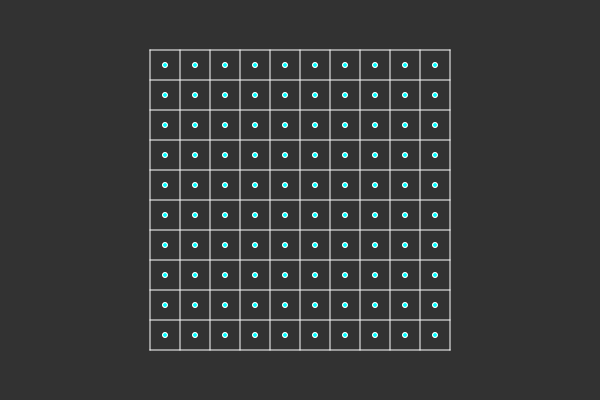
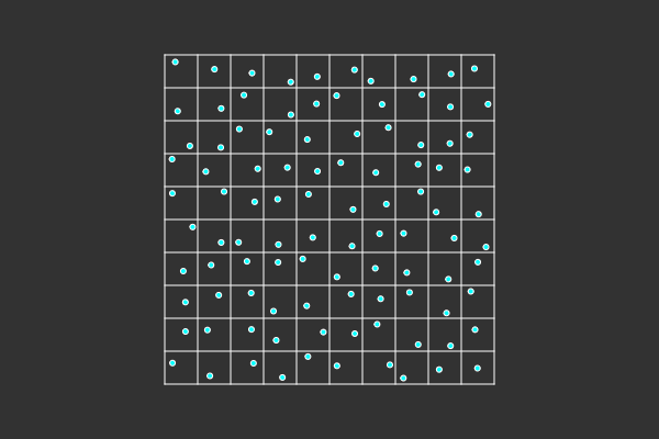
What we can do is generate positions that are on a uniform grid. It is quite simple; we have to determine the width and the height of our grass chunk, and know how many rows and columns we have. Afterward, we can apply a random offset to each point in the grid, to move it slightly. This will provide us with a uniform, but slightly random, distribution.
How do we approach this in code? Well, we can think of our seed positions as vertices. So we want to create a vertex buffer object (VBO) in OpenGL that can store all those positions. But we have to decide: how do we approach the rest of our geometry? Because, quite obviously, a blade of grass is more than its base position. Well, we have two options, and I want to cover them extensively so we know what we are doing.
What is a blade of grass?
We are, hopefully, all familiar with grass; it is in most places around the world. But how do we represent it in our graphics engine? We have to keep in mind that we won't have a single blade of grass; we will have thousands, maybe even more, and we want it running fast.
We also should keep in mind that we want to animate it later, specifically have it respond to wind and blow through it. This means we need some resolution to sell this effect. We can't just have a blade of grass exist out of a rectangle with a triangle on top, because that wouldn't look good.
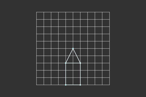
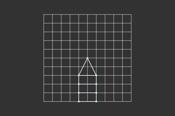
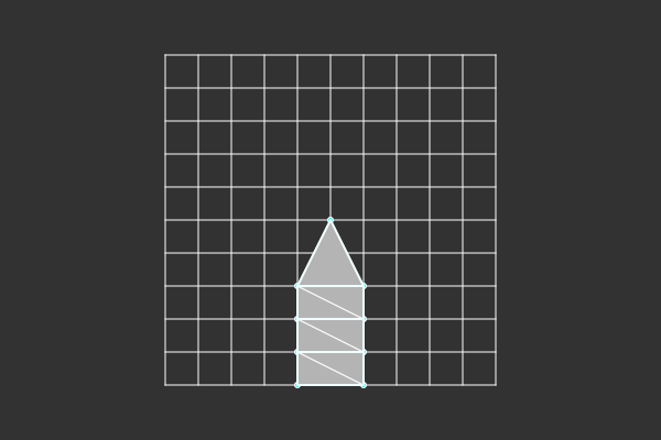
But that is the basic shape of a blade of grass—a rectangle that has a triangle on top. In its most basic form, that is three triangles. So if we want more detail, we can add more rectangles in between, meaning two triangles. The more we add, the better it will look when the grass is bending.
As for technical implementations, a triangle strip lends itself quite well here. Since we can define our vertices in a zigzag pattern, we will get the exact triangles we want.
Option #1 Geometry shader
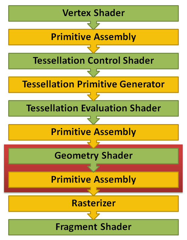
This is a step in the graphics pipeline for which we can insert our own shader. The purpose of the geometry shader is to receive some kind of input, like triangles or points, and convert them into some different kind of geometry, like a triangle list, strip or fan (and more).
The approach we could take here is the following:
- We create a VBO and fill it with vertices that are placed at the positions where we want our grass to sprout.
- We then draw that using
glDrawArrays(GL_POINTS, 0, count);. Then we go through the steps of the graphics pipeline. - First is the vertex shader; normally, we apply our MVP matrix to our vertex position to go from model to clipping position. But now we leave that for the geometry shader, since we will need to use the model position. We do still need to propagate all the vertex data to the next step in the pipeline, similar to how you communicate data from the vertex to the fragment shader (only now the geometry shader is first).
- Then we reach our geometry shader. Here we want to have points as an input and return a triangle strip. The points are the seed vertices we created earlier, and the triangle strip is the final geometry of the grass blade. A triangle strip is a good choice here, since it will save on vertices (as opposed to a triangle list), and we can construct the entire grass blade as a triangle strip.
- Finally, we reach the fragment shader, and here we can shade our grass blade as normal; apply lighting and a texture, for example.
Option #2 Precomputing the geometry
An alternative approach we can take is to precompute all our geometry beforehand in a compute shader and skip the geometry shader in its entirety. But why would we want that? On the surface, the geometry shader looks to be a pretty clean solution: we only have to generate our seed positions, we can use the geometry shader to easily 'build' our grass blades, and it allows us to use a triangle strip for a lot of grass blades with no apparent cost (I'll discuss this cost later).
So what is the issue? The geometry shader is on its way out. It is not a very performant piece of the graphics pipeline. Under the hood, it generates numerous new vertices, the ones specified in the geometry shader, and when it's done, it throws them away. Just so that in the next frame, it can generate them all over again. While it does give some flexibility if you have ever-changing geometry, it is not that simple. In the geometry shader, you predefine the maximum number of vertices you will output. So that will be the definitive cost each time you use it, so producing fewer vertices won't be cheaper. And with all the flexibility with changing vertices, you can also perform in the vertex shader.
So how do we approach this alternative?
What we want to do is create a VBO for all the vertices of our grass and send that to a compute shader, where all the vertex positions and data can be generated. Afterward, we run the vertex and fragment shaders, and can do our procedural animation in the vertex shader.
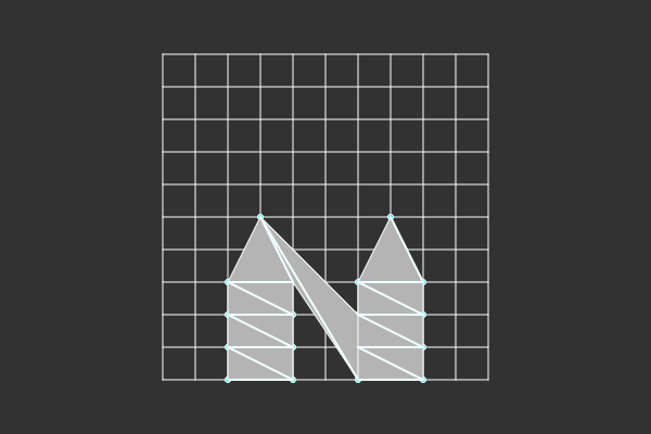
One area of caution when doing this is that the geometry shader gave us a big benefit; each point became its own triangle strip. All our data is still in one VBO so we have to use one draw call, and ideally use a triangle strip so we don't need the overhead of an index buffer. But if our entire buffer is a triangle strip, that will cause issues. This is because the triangle strip would connect each vertex, which means that the end of each blade of grass connects with the start of the next one. This didn't happen in the geometry shader because each seed point started its own primitive.
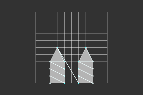
One technique to circumvent that is to make use of degenerate triangles; if we need a disconnect between two grass blades, we place an extra vertex at the tip of the blade we just finished, and an extra vertex at the base of the new one, and then we continue as usual. This will create two triangles that completely overlap with themselves. Since they completely overlap with themselves, you won't see them, and you can continue with your next blade of grass as usual.
The trade-off here is that there are 2 vertices extra per blade of grass, or induce the cost of an index buffer. But let's make sure to measure. A grass vertex has a position, normal and texture coordinate (at least, you might want to add more in the future). That is 8 floats, with 4 bytes per float, meaning 32 bytes. And since we need two extra vertices per blade of grass, that means we need 64 bytes extra per blade of grass.
With an index buffer, we need three 4-byte integers for every triangle. My grass blades currently have 13 triangles, which means 156 bytes per blade of grass. At the lowest, the grass blades will have 5 triangles, which would be 60 bytes.
But let's see how it scales before we settle on anything here.
- The index buffer gets bigger the more segments we add to our blade of grass, so if we want more detail, the index buffer would increase.
- When using the triangle strip, our size scales based on the size of our vertices, since we will add two extra vertices to every grass blade to create a degenerate triangle. So adding more data to the vertices would make this scale.
Currently, I think the blades of grass already have too many vertices; it's not likely we will make them more detailed, especially when adding LODs will reduce it even further (distant LODs will never have more than 5 vertices). While adding more data to the vertices is very possible, I can already tell that we will need to add more, especially if we are moving to precomputed geometry. So to conclude, we'll continue with a triangle list approach, instead of the triangle strip. Since this will scale best for bigger grass fields.
And for those wondering, we can also opt for using 16-bit integers instead of 32-bit ones. This would reduce the index buffer memory size by two. But then we'd have to be sure we wouldn't cross the 16-bit max value size (32,767). Which is about ~840 blades of grass (at 13 triangles). Not amazing. Comparatively, a 32-bit integer gets us about 5,000x5,000 patch of grass.
But anyhow, with the approach of creating our geometry on the GPU, we have the following consequences:
- We'll have to switch to a triangle list, which will incur some overhead because of the index buffer.
- We no longer have to calculate the position of each vertex in every frame; this is done once in our compute shader.
- We have to animate our grass blades in the vertex shader. But keep in mind that we no longer know the origin of our grass blade, since before this was the point we received as input in our geometry shader. Now we only have the vertex we work on in the vertex shader.
Creating the field
So to summarize, we need the following:
- A VBO with all the geometry.
- An Element Buffer Object (EBO) to store all the indices.
- And finally, draw it as a triangle list.
First, we have to know how big our VBO and EBO have to be. For this, we need to define some structures.
struct TerrainVertex
{
    glm::vec3 position;
    glm::vec3 normal;
    glm::vec2 textureUV;
    glm::vec2 terrainUV;
    glm::vec3 seedPosition;
};
Here, we provide the following:
- The model position of the vertex.
- The normal direction.
- The texture coordinates so we can map textures later.
- A normalized coordinate for where the grass blade is in the chunk. We will use this later to sample noise textures so we can apply wind, for example.
- And finally, the position of the base of the grass blade. Since we'll be applying animations in the vertex shader, we don't actually know, in relation to the grass blade, where the vertex is. Why we need this will become more clear later on.
Then we can define some methods to find out more information about our grass blade. First, we have to determine how many 'segments' we'll have per blade. With this, I mean the number of rectangles that form the body of our blade. The more we have of these, the more resolution we'll have when animating.
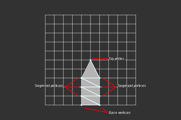
constexpr BLADE_SEGMENT_COUNT = 6;
Here, I'll just very simply set it to 6. With this information, we can determine how many vertices a blade of grass has.
// 2 base vertices, 2 vertices per segment, 1 tip vertex.
constexpr BLADE_VERTEX_COUNT = 2 + BLADE_SEGMENT_COUNT * 2 + 1;
And finally, we can determine the number of triangles in a grass blade:
// Two triangles per segment, plus one extra for the tip.
constexpr BLADE_TRIANGLE_COUNT = BLADE_SEGMENT_COUNT * 2 + 1;
Now we can define our TerrainChunk.
constexpr uint32_t GRASS_CHUNK{ 16 };

struct TerrainChunk
{
    TerrainChunk();
    TerrainChunk(uint32_t rows, uint32_t columns);

    int32_t columns;
    int32_t rows;
    glm::vec2 cellSize;

    glm::vec2 Size() const { return { columns * cellSize.x, rows * cellSize.y }; }
    uint32_t GrassCount() const { return columns * rows * GRASS_CHUNK * GRASS_CHUNK; }

private:
    friend class TerrainManager;

    unsigned int _grassVBO{}, _grassVAO{}, _grassIBO{};
};
Let's go over this:
- I create a constant for
GRASS_CHUNK, with this, I mean that each column and row in ourTerrainChunkwill exist out of a 16x16 patch of grass. This will make more sense later when we implement our compute shader, but this is a bit better aligned. And in my experience, you don't need to have the flexibility to be able to remove one row or column of singular grass blades. - Then we define our
rowsandcolumns. cellSize: We also set acellSize, with this, we will have some control over how big our terrain chunk will be.Size(): We create a method to get the actual size by combining thecellSizewith rows and columns.GrassCount(): And we add another method to determine the amount of grass in the chunk.- I also added the OpenGL handles to this class, so they stay related to the instance.
Now we can start allocating and creating VBO and EBO. For completeness, I'll show the OpenGL code for creating and binding the VBO, EBO and VAO.
// Generate buffers.
glGenVertexArrays(1, &terrain._grassVAO);
glGenBuffers(1, &terrain._grassVBO);
glGenBuffers(1, &terrain._grassIBO);


// Bind buffers.
glBindVertexArray(terrain._grassVAO);
glBindBuffer(GL_ELEMENT_ARRAY_BUFFER, terrain._grassIBO);
glBindBuffer(GL_ARRAY_BUFFER, terrain._grassVBO);

// How OpenGL should interpret the data.
uint32_t index{0};
glEnableVertexAttribArray(index);
glVertexAttribPointer(index, 3, GL_FLOAT, GL_FALSE, sizeof(TerrainVertex), reinterpret_cast<void*>(offsetof(TerrainVertex, position)));

glEnableVertexAttribArray(++index);
glVertexAttribPointer(index, 3, GL_FLOAT, GL_FALSE, sizeof(TerrainVertex), reinterpret_cast<void*>(offsetof(TerrainVertex, normal)));

glEnableVertexAttribArray(++index);
glVertexAttribPointer(index, 2, GL_FLOAT, GL_FALSE, sizeof(TerrainVertex), reinterpret_cast<void*>(offsetof(TerrainVertex, textureUV)));

glEnableVertexAttribArray(++index);
glVertexAttribPointer(index, 2, GL_FLOAT, GL_FALSE, sizeof(TerrainVertex), reinterpret_cast<void*>(offsetof(TerrainVertex, terrainUV)));

glEnableVertexAttribArray(++index);
glVertexAttribPointer(index, 3, GL_FLOAT, GL_FALSE, sizeof(TerrainVertex), reinterpret_cast<void*>(offsetof(TerrainVertex, seedPosition)));

// Unbind buffer.
glBindVertexArray(0);
glBindBuffer(GL_ARRAY_BUFFER, 0);
I make use of the offsetof macro to determine the distance number of bytes for a variable in a struct.
uint32_t grassCount{terrain.GrassCount()};
uint32_t vertexCount{grassCount * BLADE_VERTEX_COUNT(terrain.currentLOD)};
uint32_t indexCount{grassCount * BLADE_TRIANGLE_COUNT(terrain.currentLOD) * 3};
Here we get our local variables for the amount of grass, the number of vertices, and the number of indices (3 per triangle), in total for our TerrainChunk.
glBindBuffer(GL_ARRAY_BUFFER, terrain._grassVBO);
glBufferData(GL_ARRAY_BUFFER, sizeof(TerrainVertex) * vertexCount, nullptr, GL_STATIC_DRAW);

glBindBuffer(GL_ELEMENT_ARRAY_BUFFER, terrain._grassIBO);
glBufferData(GL_ELEMENT_ARRAY_BUFFER, sizeof(uint32_t) * indexCount, nullptr, GL_STATIC_DRAW);
The size of our VBO will then be the number of vertices times the size of a vertex. And our element buffer will be the number of indices times the size of our integer.
And with that, we now have a buffer for our vertices and indices, to exactly fit the amount of grass we need. But there is one slight problem: we have no actual data that even looks remotely like grass... Let's fix that!
Making grass
While we can generate all this geometry on the CPU, performing it on the GPU has several benefits:
- We don't have to copy anything; our buffers (VBO and EBO) already exist on the GPU; if we generate on the CPU, we'd have to copy all that data. But if we generate on the GPU, we don't have to do that at all.
- All the grass blades are very similar, with just slight differences; this hints that it can be done concurrently.
- Performing this all concurrently will be a lot faster than doing it on the CPU.
So let's write our kernel! (A kernel is a function that is run on the GPU.)
We have to provide our VBO and EBO, since those are the locations we are writing to. We will also need to send our TerrainChunk since that contains all the specifics about how to generate it.
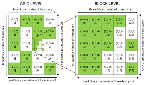
In CUDA (and most other compute shader APIs), you can launch a kernel with a predefined number of threads and blocks. A thread group exists of out of threads, a block exists out of thread groups, and all the blocks make up what is called a grid. So before we launch our kernel, we need to provide it with the size of thread groups and blocks. Well, we did some preparation for this already; we can say that our thread group is 16x16, or the same as how we defined our GRASS_CHUNK constant.
Then we can make our block size equal to the rows and columns in the TerrainChunk. And this then matches exactly to the grass count we computed before.
dim3 threads{GRASS_CHUNK, GRASS_CHUNK};
dim3 blocks{static_cast<uint32_t>(terrain.columns), static_cast<uint32_t>(terrain.rows)}
With that information, we can launch our kernel:
InitTerrainKernel<<<blocks, threads>>>(device_terrainVBO, device_terrainEBO, terrain.cellSize.x / GRASS_CHUNK,
  terrain.cellSize.y / GRASS_CHUNK);
We are passing our VBO and EBO device pointers. Device pointer is a concept in CUDA that means that the pointer points to some data that is located on the GPU. They can only be accessed through a kernel. We also pass the cellSize divided by GRASS_CHUNK, this means that we have the size of what a single grass blade can occupy.
Our kernel so far looks like the following:
__global__
void InitTerrainKernel(bee::TerrainVertex* terrainVBO, uint32_t* terrainIBO, float cellSizeX, float cellSizeY)
{
  // ...
}
Using some of the CUDA constants, we can determine what our x and y positions are within the kernel:
uint32_t x{threadIdx.x + blockIdx.x * blockDim.x};
uint32_t y{threadIdx.y + blockIdx.y * blockDim.y};
The threadId is the position of the thread we are in, and the blockId is the position of the block we are in. Using blockDim we can flatten this out to our absolute x and y positions. We can use this information to identify which blade of grass we are. Remember that we run this kernel for each blade of grass.
But to do something meaningful, we have to find where in the VBO (and EBO) we can start writing our data. Our VBO is just a big buffer of vertices. So, we can use our constant BLADE_VERTEX_COUNT times our position to figure out where it is.
First, we have to flatten our x and y positions to a single number:
uint32_t dataOffset{x + y * blockDim.x * gridDim.x};
This is similar to how you flatten a 2D array to a single index. Each row is the size of blockDim.x * gridDim.x and we multiply that by our y variable. And we add our x to get the final solution.
This dataOffset can be seen as the ID of the blade of grass we are working on. And we can use that to index our buffers. However, our buffers are of vertices, and a blade of grass has multiple vertices.
uint32_t vertexOffset{dataOffset * BLADE_VERTEX_COUNT};
And with that, we can now start indexing our terrainVBO pointer!
Let's get the indexing for our EBO out of the way as well.
uint32_t perBladeIndexCount{BLADE_TRIANGLE_COUNT * 3};
uint32_t indexOffset{dataOffset * perBladeIndexCount};
Using our BLADE_TRIANGLE_COUNT constant, we know the number of triangles per blade of grass, and by multiplying it by three, we know the number of vertices.
And this is the number of indices we have per blade of grass, so we can multiply that by our dataOffset to get the final indexOffset which we can use to start indexing our terrainEBO.
First, we'll need our seed position, which is essentially what the origin of our grass blade will be.
float3 basePosition{ x * cellSizeX, 0.0f, y * cellSizeY };
For this, we can simply use our thread x and y id's and scale them by our cell sizes.
We can then use this to assign our base vertices. These are the first two vertices in our VBO and are rooted in the ground.
// Returns the width for an index of the model.
// (By height, so base would 0 and the tip the last.)
__device__
float WidthForIndex(size_t i) { return sqrtf(BLADE_SEGMENT_COUNT - (i / 2)) * 0.01f + 0.025f; }
This function uses a square root curve to let the vertices come together as we progress to the tip. You can play around with these numbers to get something you like.
float baseWidth = WidthForIndex(0);
terrainVBO[vertexOffset + 0].position.x = -baseWidth + basePosition.x;
terrainVBO[vertexOffset + 0].position.y = basePosition.y;
terrainVBO[vertexOffset + 0].position.z = basePosition.z;

terrainVBO[vertexOffset + 1].position.x = baseWidth + basePosition.x;
terrainVBO[vertexOffset + 1].position.y = basePosition.y;
terrainVBO[vertexOffset + 1].position.z = basePosition.z;
We use our vertexOffset to index our VBO and a WidthForIndex function that calculates the width between the two vertices using a square root function.
We can then continue with the remaining vertices, this is based on our BLADE_SEGMENT_COUNT, so it is best that we use a for loop for this.
const float totalHeight = 1.0f;
const float segmentHeight = totalHeight / (BLADE_SEGMENT_COUNT + 1);

for (uint32_t i = 0; i < BLADE_SEGMENT_COUNT * 2; i += 2)
{
    float width = WidthForIndex(i);
    float height = (i + 2) / 2.0f * segmentHeight;

    terrainVBO[vertexOffset + i + 2].position.x = -width + basePosition.x;
    terrainVBO[vertexOffset + i + 2].position.y = height + basePosition.y;
    terrainVBO[vertexOffset + i + 2].position.z = basePosition.z;

    terrainVBO[vertexOffset + i + 3].position.x = width + basePosition.x;
    terrainVBO[vertexOffset + i + 3].position.y = height + basePosition.y;
    terrainVBO[vertexOffset + i + 3].position.z = basePosition.z;
}
Here we iterate until we reach the BLADE_SEGMENT_COUNT and do a step of two per iteration.
We can index our VBO by using the vertexOffset and adding a constant of 2 and 3. We use this since we already assigned indices 0 and 1 to our base vertices. We can use our WidthForIndex function again to get our new width value, and with that, we compute the position.
And finally, we can implement the vertex for the tip. (This is after doing the for loop.)
terrainVBO[vertexOffset + bladeVertexCount - 1].position.x = basePosition.x;
terrainVBO[vertexOffset + bladeVertexCount - 1].position.y = basePosition.y + totalHeight;
terrainVBO[vertexOffset + bladeVertexCount - 1].position.z = basePosition.z;
With this, we have our positions figured out, and we just need the indices to get the bare minimum. The indices start to get a bit more complicated, so I'll try to make it clear.
First, we get back to our for loop.
for (uint32_t i = 0; i < BLADE_SEGMENT_COUNT * 2; i += 2)
{
  // ... Assign vertex positions.

  uint32_t firstTriangleIndex{(i + 1) * 3};
  terrainEBO[indexOffset + firstTriangleIndex + 0] = vertexOffset + i + 0;
  terrainEBO[indexOffset + firstTriangleIndex + 1] = vertexOffset + i + 1;
  terrainEBO[indexOffset + firstTriangleIndex + 2] = vertexOffset + i + 2;

  uint32_t secondTriangleIndex{i * 3};
  terrainEBO[indexOffset + secondTriangleIndex + 0] = vertexOffset + i + 1;
  terrainEBO[indexOffset + secondTriangleIndex + 1] = vertexOffset + i + 3;
  terrainEBO[indexOffset + secondTriangleIndex + 2] = vertexOffset + i + 2;
}
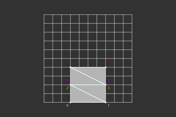
Per segment, we have two triangles we need indices for. These are separated by the new line. Our first triangle index, can be found by incrementing our index by 1 and multiplying by 3 (for the number of indices in a triangle). So firstTriangleIndex is the position from the indexOffset for our first triangle. So when you add them all up together, you can use it to find the first triangle in our EBO. We can index the entire triangle by doing + 0, + 1, + 2.
Now that we know where our triangle indices are, we have to assign the index of the vertex that should be there. And we also have to assign them in the correct winding order (counter-clockwise for OpenGL)
So we know that each iteration in the for loop creates one segment in the grass blade. That is one quad, meaning two triangles. So, similar as to how we indexed our VBO, we can use the same approach for finding the indices for our EBO. vertexOffset + i is the first vertex of our segment. And then we can add 0 through 3, to find the indices of the quad. 0, 1, 2 for the first triangle, and 1, 3, 2 for the second triangle.
And finally, we need one more triangle for the tip of our grass blade.
terrainEBO[indexOffset + perBladeIndexCount - 3] = 0 + (bladeVertexCount - 3) + vertexOffset;
terrainEBO[indexOffset + perBladeIndexCount - 2] = 1 + (bladeVertexCount - 3) + vertexOffset;
terrainEBO[indexOffset + perBladeIndexCount - 1] = 2 + (bladeVertexCount - 3) + vertexOffset;
We find the last triangle by subtracting from the maximum number of indices in the EBO. And we do the same for assigning the vertices; we subtract from the maximum number of vertices in a blade and get the last three indices.
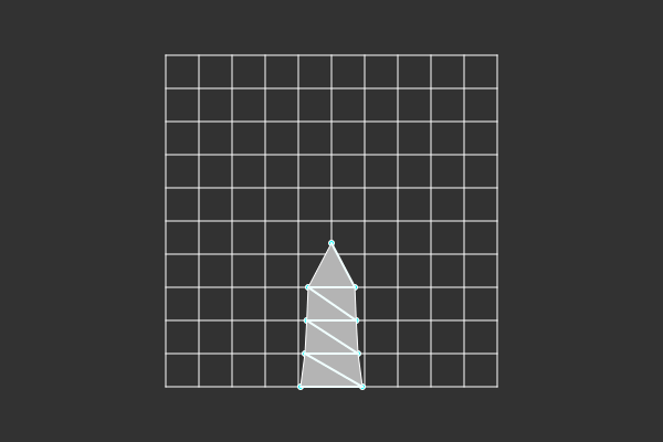
With this, we have figured out the positions for all vertices and indices to create the triangles. If you add a simple vertex and fragment shader, you can start drawing the terrain. For the vertex shader, you just have to convert model space to clipping space using an MVP matrix. And in the fragment shader you can't do much more than add draw it with an unlit color, for now.
uint32_t indexCount{grassCount * BLADE_TRIANGLE_COUNT * 3};
glDrawElements(GL_TRIANGLES, indexCount, GL_UNSIGNED_INT, 0);
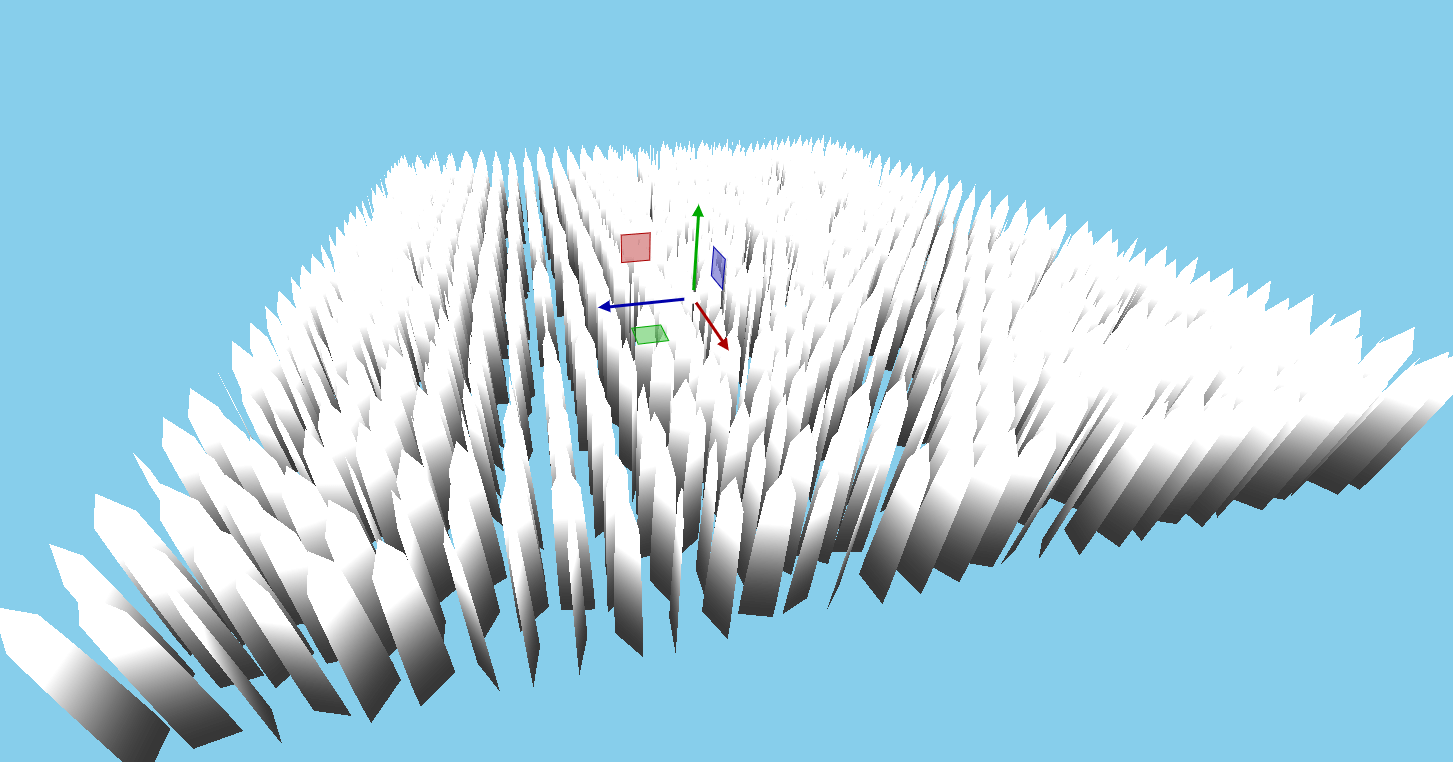

And with that we have created the geometry for our grass. Currently, it is looking very basic. It is really just a bunch of upwards points planes with a point. But with some imagination you can see where this is heading. It is quite a complicated subject and I want to be as complete as possible.
I hope you've learned something about the differences in using primitives and what costs there are. And also that moving computations to the GPU can result in a very big optimizations. But that you also have to keep in mind with what data you are working. Most of the time you can't move something as is to a different environment. Like when we discussed the geometry shader, there are quite differences between the approaches, although the result is the same.